|
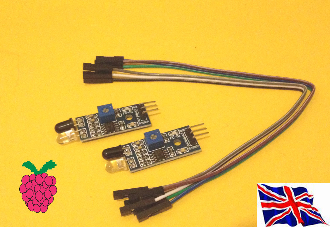
Trace- IR set 2 module with 6 x 20cm male to male cable
Module Description The light sensor module adaptable to the environment, having a pair of infrared transmitter and receiver, launch tube a certain frequency, infrared, when the obstacle detection direction (reflection surface), the infrared receiver is reflected back by the receiver tube, after processing through the comparator circuit, the green indicator light will illuminate while the signal output interface output digital signal (a low-level signal) can be adjusted via potentiometer knob detection distance, the effective distance range 2 ~ 30cm, working voltage is 3.3V-5V. The detection range of the sensor can be adjusted via potentiometer, with little interference, easy to assemble, easy to use, can be widely used in robot obstacle avoidance, obstacle avoidance trolley line counts, and black and white line tracking, and many other occasions. Module Parameter Description When the module detects an obstacle in front of the signal, the circuit board green indicator light levels while continuing output low signal OUT port, the module detects the distance 2 ~ 30cm, detection angle 35 °, the distance can detect potential control to adjust, adjust potentiometer clockwise, the detection distance increases; counterclockwise adjustment potentiometer, detection distance decreases. 2, the sensor active infrared reflection survey, so the target reflectivity and shape of the detection range of the key. The minimum detection distance which black and white max; small area of the object distance is small, a large area from the Grand. 3, the sensor module output port OUT can be directly connected to the microcontroller IO port, but also can directly drive a 5V relay; Connection: VCC-VCC; GND-GND; OUT-IO 4, the comparator using LM393, job stability; 5, can be 3-5V DC power supply for the module. When the power is turned on, the red power indicator light; 6, with 3mm screw holes for easy mounting, installation; 7, the circuit board size: 3.2CM * 1.4CM 8, each module is shipped already comparing the threshold voltage adjustable via potentiometer good, non-exceptional circumstances, do not arbitrarily adjust the potentiometer. Support our scratch driver software, can be easy use in scratch
broadcast "TRACEIRINIT" +"17" GPIO number & "TRACEIRINIT" +"18" in Sensing --> Slider , you will see the "TraceIR-17" & "TraceIR-18" in the list |
i2c MCP23017 GPIO mode Command "i2"+ "address(1-8)" + "a" +"in" for Port A Command "i2"+ "address(1-8)" + "b" +"in" for Port B Address 20 --> 1 21 --> 2 22-->3 23 -->4 Address 24 --> 5 25 --> 6 26-->7 27 -->8 command "i22bin" initial address 21, Port B as input (1)"i22bin" initial address 21, Port B as input (2) broadcast "Update" (3) in Sensing --> Slider , you will see the " I2C1B-0 ~ I2C1B-7" in the list Python test program use GPIO 17, GPIO 18
|