|
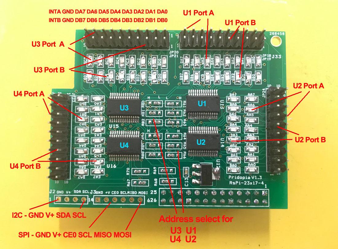
1 JP18 GA0 ~ GA7 U13 Port A &JP19 GB0 ~ GB7 U13 Port B 2. JP25 AA0 ~ AA7 U14 Port A JP24 BA0 ~ BA7 U14 Port B 3. JP20 GC0 ~ GC7 U15 Port A JP21 GD0 ~ GD7 U15 Port B 4. JP22 DA0 ~ DA7 U16 Port A JP23 EA0 ~ EA7 U16 Port B 5. R61,R62,R63 ( for U13 Address select A0,A1,A2 ) 6. R64,R65,R66 ( for U14 Address select A0,A1,A2) 7 R80, R81,R82 ( for U15 Address select A0,A1,A2 ) 8. R88,R89,R90 ( for U16 Address select A0,A1,A2) 9. U13 (000) 23s17 -1 Port A,B U14 (001) 23s17-2 Port A,B 10. U15 (002) 23s17 -3 Port A,B U16 (003) 23s17-4 Port A,B
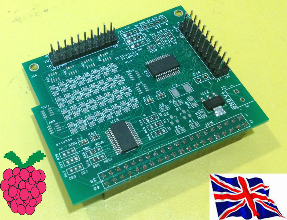
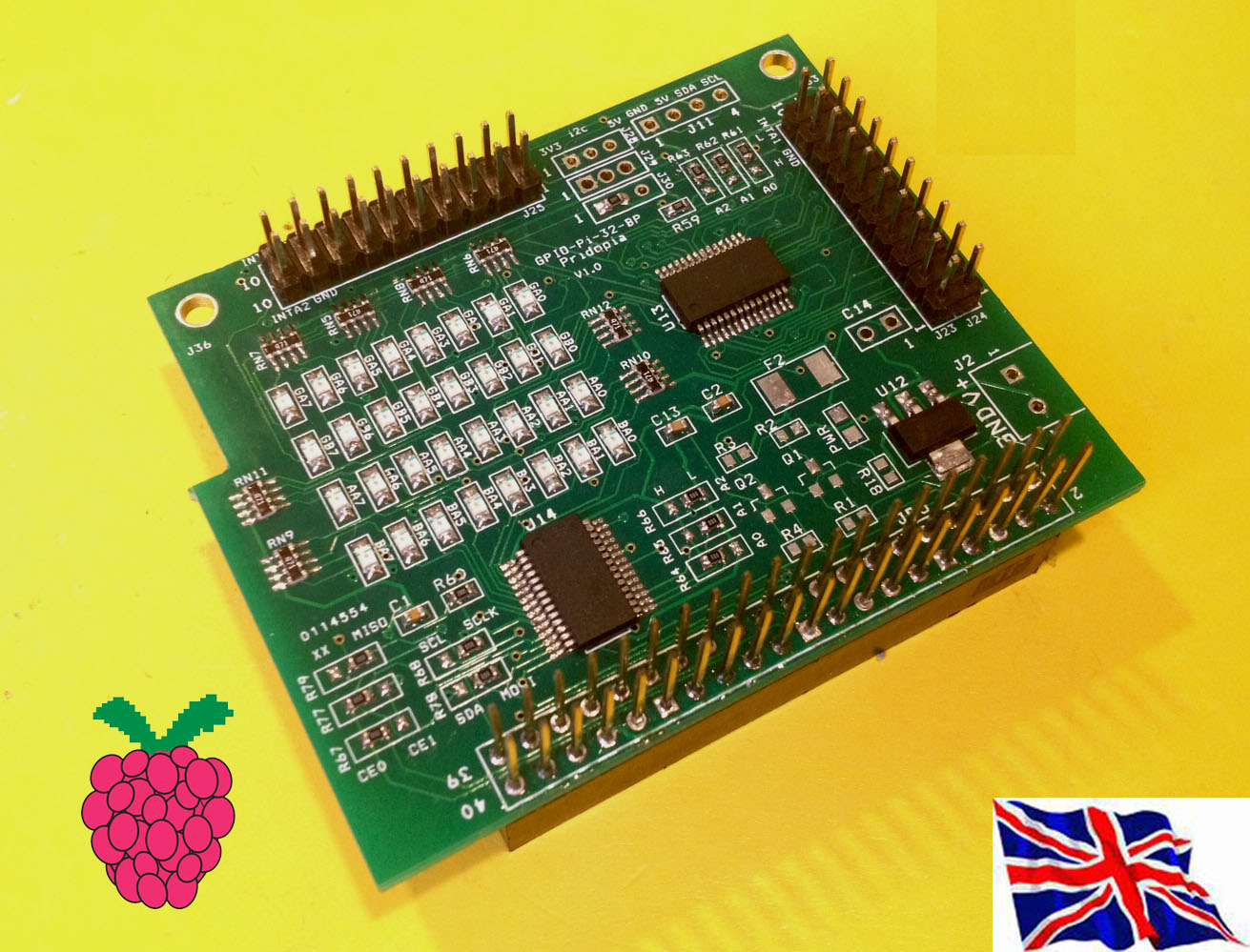
23s17-4 - 64 GPIO board plug in Raspberry Pi Model B+ / B2 / B3
23s17-4 plug in Raspberry Pi with our Rs-Pi 4Hub board 64 Blue LED "ON"
new test program 23s17-4port-v3.py demo
|
new test program 23s17-4port-s-v103.py demo
new GUI interface output software 23s17-4port-GUI.py demo Support our Pi_Scratch software
U1 to U4 spi 23s17 address 40,42,44,46
U1 to U2 spi 23s17 address 40,42
40 --> 1 42 --> 2 44 --> 3 46 --> 4
48 --> 5 4a --> 6 4c --> 7 4e --> 8
Command "sp"+ "address(1-8)" + "a" +"bit(1 to 8)" for Port A
Command "sp"+ "address(1-8)" + "b" +"bit(1 to 8)" for Port B
Command "bits"+ "address(1-8)" + "a" +"bit(8 to 1)" for Port A
Command "bits"+ "address(1-8)" + "b" +"bit(8 to 1)" for Port
sp2b7 --> spi address 2 Port B bit 7 ON/OFF
sp3b4 --> spi address 3 Port B bit 4 ON/OFF
bits2b01010101 --> address 2 port B from bit 8 to 11
--> 01010101
bits2a01010101 --> address 2 port A from bit 8 to 1
output --> 01010101
bits2aoff --> address 2 Port A all OFF/clear
bits2aclr --> address 2 Port A all OFF/clear
|