|
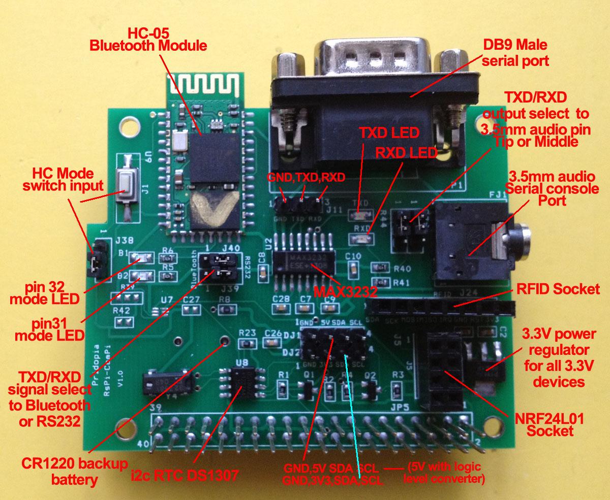
Raspberry Pi - RS232 COM & Serial console & BlueTooth console Board 1. provide DB9 male COM port 2. provide i2c DS1307 RTC with CR1220 bauk-up battery 3. provide RFID socket ( SPI signal) / NRF24L01 socket (SPI signal) you can choose use RFID or NRF24L01 ( both use SPI signal) 4. Provide 2 extra i2c device input port, one for 3.3V, one for 5V (with Logic Level converter) 5. provide 3.3V power Regulator for 3.3V device ( RFID/ NRF24L01) i2c device 6. provide 3.5mm serial console cable socket, 7. provide jumper setting can change 3.5mm output TX, RX position. 8 HC-05 Bluetooth module Datasheet
1. Pi Setting for standard RS232 COM port function setting 2. Pi Setting serial console port for bluetooth Step 1. Modify the inittab File: sudo nano /etc/inittab change to #Spawn a getty on Raspberry Pi serial line Step 2. sudo nano /boot/cmdline.txt The entire contents of the file look like this: dwc_otg.lpm_enable=0 console=ttyAMA0,115200 kgdboc=ttyAMA0,115200 console=tty1 root=/dev/mmcblk0p2 rootfstype=ext4 elevator=deadline rootwait change to dwc_otg.lpm_enable=0 console=ttyAMA0,9600 kgdboc=ttyAMA0,9600 console=tty1 root=/dev/mmcblk0p2 rootfstype=ext4 elevator=deadline rootwait Step 3 .Bluetooth setting for console port
use Android Tablet BlueTerm+ or BlueTerm find "HC-05" bluetooth device
input pin "1234" for pair |
you will see raspberry pi boot from Android Tablet screen B2 LED flashing, B1 always On 3.5mm serial console cable setting for serial console function you can setting 9600 or default 115200 RS232 console setting 3.5mm serial console cable
RFID reader demo the RFID socket we use CE0 for signal
1)Command "RFID"+"INIT"+"0" will initial SPI signal to active RFID Reader 2) you will see "LastRFID" & "RFID" in Sensors
NRF24L01 demo NRF24L01 WiFi Scanner demo |