|
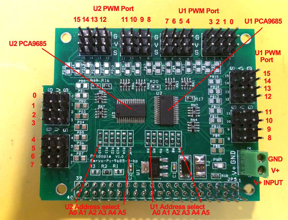
The PCA9685 is an I2C-bus controlled 16-channel LED controller optimized for LCD PCA9685 also has a built-in oscillator for the PWM control. The PCA9685 has 4096 steps (12-bit PWM) 1. J2 2P Terminal Block 5V input for PWM V+ 2. U2 PCA9685 (PWM Port 0 ~ 15) 3. R4,R5,R6,R7R8,R9( for U2 Address select A0,A1,A2,A3,A4,A5) 4. U3 PCA9685 (PWM Port 0 ~ 15) 5. R10,R11,R12,R13,R14,R15( for U3 Address select A0,A1,A2,A3,A4,A5) 6.Red power-good V+ LED 7. 1.6A PolySwitch Fuse for V+ input protect.
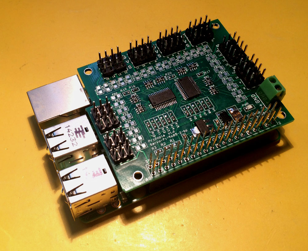
plug in Raspberry Pi with Servo motor
in i2cdetect you can found 2 device in system (40,41) (1) Servo Motor control 2 Servo in channel 0 & channel 7 Command "SE"+ "PWM (0-15)" + "a" +"angle" for Address 41
se7a10 --> channel 7 servo move 10 angle address 41
se7a-10 --> channel 7 servo move -10 angle address 41
se0a10 --> channel 0 servo move 10 angle address 41
se0a-10 --> channel 0 servo move -10 angle address 41
|
(2) PWM LED output demo
LED module (Blue, Green,Yellow,Red) LED Scrolling Command PWMLED41S0E15D4True PWMLED”Address” S[Start channel] E[End channel] D[Delay / Timing] [True/False] Address 40, 41, 42, 43, 44 Start channel & End channel 0 ~ 15 16 channel D 1,2,3,4,5 (1 ~ 100) Delay Timing LED Brightness control Command PWMLED “Address” “B” “0 ~ 1000“ PWMLED41B1000 Stop command "PWMLED41STOP" |