|
Purpose:
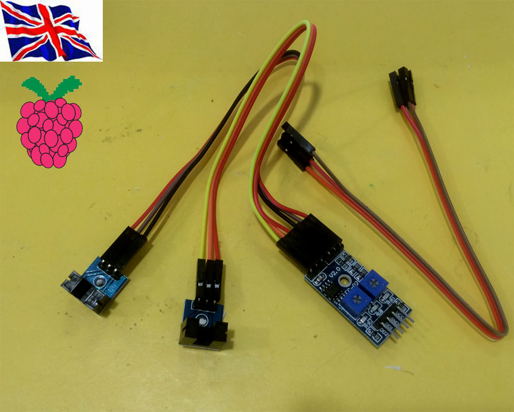
(1) module slot unobstructed, the receiver tube is turned on, the module DO output low, cover when, DO output high.
can also be connected with the active buzzer module, composed of alarm.
(1) GPIO wheel Encoder
|
Python WheelEncoder.py DEMO Python WheelEncoder.py DEMO Sudo python WheelEncoder.py 17 3 23 17 GPIO for Encoder 3 Rotation 23 Motor connect to GPIO 23 Support our Pi_Scratch software Scratch control demo Command “23” + “MOTORDIS” “17”+ “S” + “3” 17 GPIO for Encoder 3 Rotation 23 Motor connect to GPIO 23 (2) i2c 23017 GPIO wheel Encoder i2c wheel encoder python I2Wheel.py demo Sudo python I2Wheel.py 21 A 2 17 5 21 = Address of the I2C 23017 A = Bank A 2 = Bit 2 / pin 2 (1 - 8) 17 = GPIO Pin 17 , 18 for motor control through our L293D Motor control board 2 = Rotate 2 times. Scratch control demo Command format I2MOTORDIS[Address][Bank][Encoder Pin]M[Motor Pin]R[Rotations] I2MOTORDIS21A2M17R2 1. Address = 20 - 27, Address for the I2C 2. DeviceBank = A or B ( Bank for the encoder ) 3. Encoder Pin = 1 - 8 ( Pin number for the encoder ) 4. Motor Pin = GPIO Pin number for the Motor
For example our Motor Board use GPIO 17 & 18
control 2 Motor forward & backward
5. Rotations = How many rotations you want the Motor to do before it stops. minimum input 0.2 |