For beginners you can start with IoT Pi-R1 , use the on board relay control for the ON/OFF through the Internet ( you must have Internet with your Pi Wifi or Ethernet), All of our boards for the IoT Pi system have a model number & serial number that will need to match with our IoT Cloud database, our IoT Pi software runs in Pi furthermore it will detect the system and detect which type module board plug-in, and enable the function to collect the data & update to IoT Cloud.
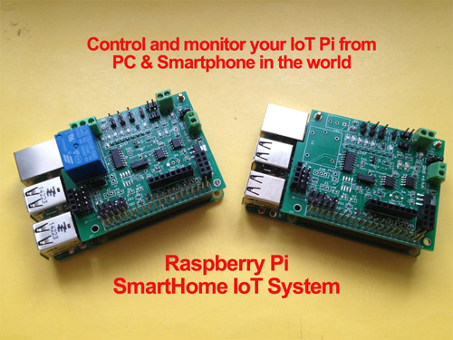
The SmartHome IoT Pi project is aimed towards creating a system capable of controlling devices over the internet from any device.
Currently the system supports up to 12 Controlled devices and 1 DHT 2302/22 Temperature and Humidity Sensor. The main device ( G1 ) Can be triggered by
temperature (with a DHT sensor) or time. The system uses Solid State Relays ( SSR ) or Switching Relays, The Switching Relays are louder and sound a "Click" when they switch.
The Switching Relays also cannot support up to 20Amps or 40Amps like the SSR's can do. The system can be deployed to control your air conditioning during
the hot summers or electronic heaters during the winter, another use would be to wire the system up to your house lights / power and control your lights
from over the internet.
Additional items are the Yellow/Blue 0.96” 128x64 OLED LCD screen to show extra info, last command sent and a countdown to update / check server status and also show Temperature and Humidity.
The advantage to using our system over another system is that everything is built for each other ( The Temperature sensors, the relays, and the screen ).
The system uses the internet through WiFi or an Ethernet cable to connect to our secure servers which enable the website interface and the Smartphone to easily communicate with your device.
SmartHome IoT Web Service ID : Demo Password : Password
1. GBR00000002 B+ ( SmartHome IoT board with all module full function, with sensor)
2. GBR00000003 B+ ( SmartHome IoT board only, with sensor)
3. GBR12345678 B2 ( SmartHome IoT board with all module full function, with sensor)
4. TWN00000001 B+ ( SmartHome IoT board with all module full function, with sensor)
SmartHome IoT Cloud Service web site
basic web base control interface (IoT Pi Board & Sensor)
IoT-Pi System
Basic IoT-Pi-R1 system with sensor & relay no extra module board
1. IoTPi-R1 SmartHome System Board
2. Pi-SmartHome IoT Pi System DC 5.0V system power voltage meter
3. HTU21D Humidity & Temperature Sensor
4. DHT22 Humidity & Temperature sensor
5. GPIO output to 4 relay board
6. Switch & System LED board
7. BMP085/180 Barometric Pressure/Temp/Altitude Sensor
8. Extra GPIO output to 4relay board9
9. IoT-Power board for system, relay & sensor
10. Mini fan for IoT-Pi system
11. DC 12V input
IoT-PW-Ext
new IoT-PW-Ext layout on board Switch and LED(5) , and all sensor(1,2,3,4) socket
IoT-Power new Ver layoutto IoT-Pw-Ext 68mm x 89mm will be easy for you to connect all sensor ,LCD, relay, Switch , System status LED to IoT-Pi-R0/R1 system board
function include
1. DC 19V ~ DC 7.2V input output to 5V & 3.3V for system use
2. extra 4 GPIO output to 4 relay
3. HTU21D Humidity & Temperature Sensor socket
4. DHT22 Humidity & Temperature Sensor socket
5. BMP180 Barometric Pressure/Temp/Altitude Sensor socket
6. Switch & System LED on board
7. 0.96” 128x64 OLED LCD monitor socket
8. NRF24L01 RF module socket
9. ESP8266Wifi module socket
10. Bluetooth module socket
11. RFID reader module socket
12. use 2x40 GPIO cable connect to IoT-Pi-R0/R1 system board
Launch a a Program
support user define program mode ( will automatic create Python Program with simply way)
The program can be trigger by Timer, Temperature sensor or run instantly.
6 GPIO , 6 Extra GPIO & delay basic function example code
delay timing setting
Step Motor control ( need Step Motor & Servo Motor module )
GPIO output control ( need GPIO module board )
Servo Motor control ( need Step Motor & Servo Motor module )
RGB-W LED light control ( need RGB-W LED module )
mobile base web control interface
support NRF24L01 RF module for wireless control function
You can add more extra function modules to enable in control panel , just use 1x4 female to female 20cm cable to connect the module you need
You also can choose with 2x40 Header - A 2x40 with 12mm high , B 2x20 with 3mm high
all modules can be work along with Raspberry Pi B+ & B2
all IoT modules can be stack plug-in together
(1) i2c 1-Wire Temperature module board
1-Wire 8 bus port (8 input port) Sensor Board (IoT-1Wire-8)
1-Wire 1 bus ( 5 input port) Sensor Board (IoT-1Wire-1)
The 18bit ADC to work as a single ended A/D converter using the internal 2.048V reference voltage with the -V pins tied to ground. A voltage divider extension board plug-in brings the input voltage range to a much more useful 0 – 5.06V. In this configuration the sample size is 17 bits for each channel.
with RGB-W LED light module will enable RGB-W control panel
(5) Multi DC Adapter Board
output Provide 5V (USB connect) , 5V,3.3V,GND through 1x8 2.54mm socket
IoT-Pi-PW-Ext new Power and sensor board layout
(6) Sensorssors
1. 5V Mini Cooling Fan
2. DHT22 Temp & Humidity Sensor
3.BMP180 Barometric Pressure/Temp/Altitude Sensor
4.HUT21 Temp & Humidity Sensor
(7) LCD & Switch
Yellow/Blue 0.96” 128x64 OLED LCD monitor support
1. Press the key shut down the system
Press the key for hold 5 seconds, system will reboot
2. Green LED flashing meaning system running
SmartHome IoT Pi System Example
This Smarthome IoT Pi System in the day time the power from battery also solar panel charger the battery, at night time use the battery, with emergency backup DC adapter for charge battery. ( the solar charger will stop charge at 14.4V, stop power supply at 10.8V, voltage of resume power supply at 12.6V. )
with on board Temp sensor can control the Mini fan
SmartHome IoT Web Service ID : Demo Password : Password
Full function control panel enable all modules
HISG (Heat Insulation Solar Glass) for DC Power input
panel size( 100cmm x 53cm) with windows frame (110cm x66cm)
1. DC input from Solar Panel DC70.7V , 370mA
2. Pi-SmartHome IoT Pi System DC 13.6V 200mA total system power draw
3. Solar Panel Battery Charger
3-1 Solar Charge in Voltage 14.1V 3-2 Battery Voltage 13.4V
4. Yuasa NP7-12 12V 7Ah Battery x3
5. Solar power input inverter (input DC
6. SSR AC control socket
7. Backup DC adapter
8,9. 2 plant for soil sensor detect
10. 18B20 temperature sensor x3
11. BMP085/180 Barometric Pressure/Temp/Altitude Sensor
12,13. Soil Probe sensor ( soil moisture sensor)
14. Micro Servo Motor
15. 5V Step Motor x2
16. DHT22 Humidity & Temperature sensor
17. 4 Relay output board
18. 1-Wire module board
19. Super AD/DA board
20. 16 channel GPIO & 16 channel PWM module board
21. RGB-W LED module board
22. Voltage detect board
23. HTU21D Humidity & Temperature Sensor
24. DC Power module board
25. Yellow/Blue 0.96” 128x64 OLED LCD monitor
26. SmartHome IoT Pi System Board with Mini Fan & Switch-LED board